Author: C.T.H

  • Goldring Lenco GL72 Restoration

    Goldring Lenco GL72 Restoration

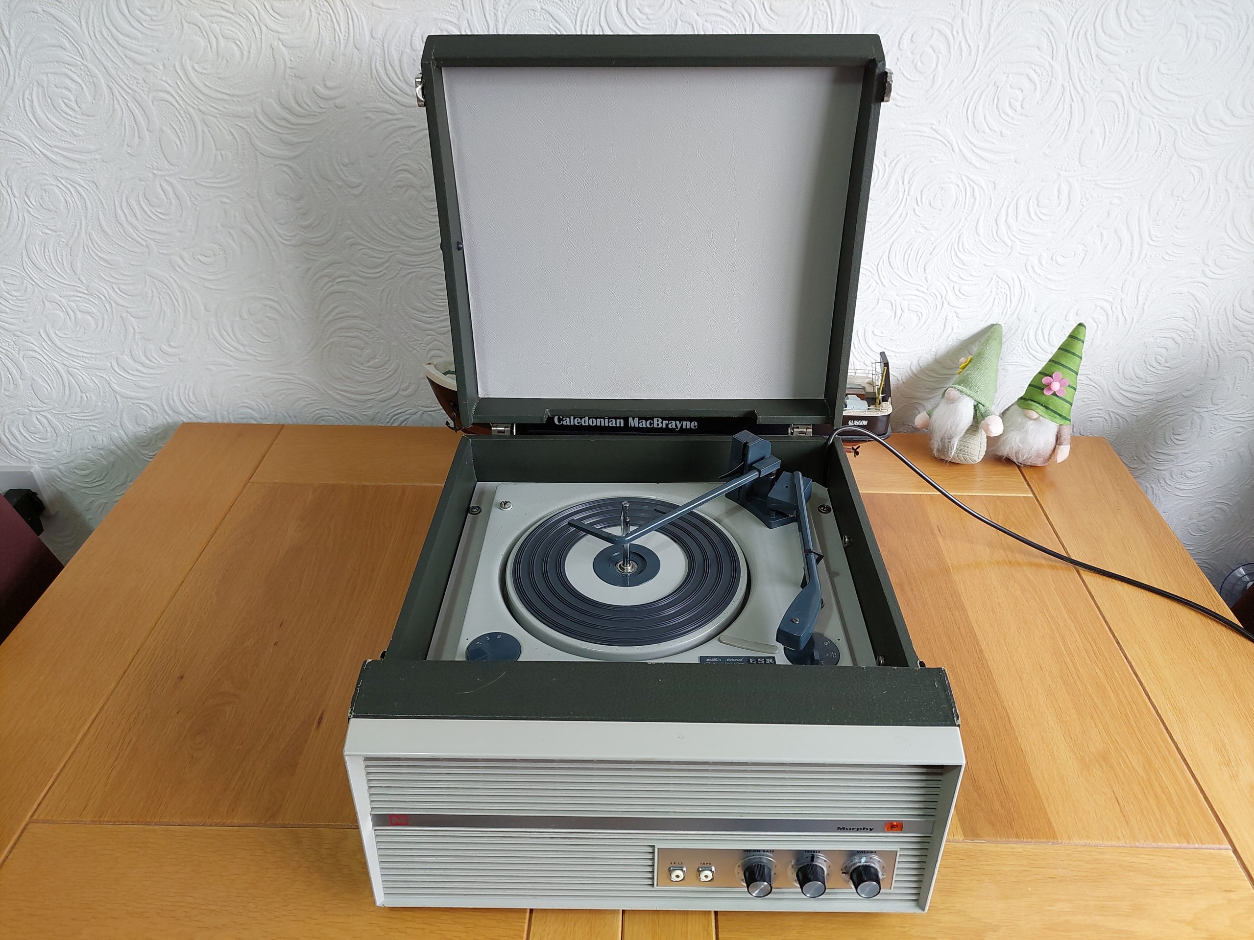
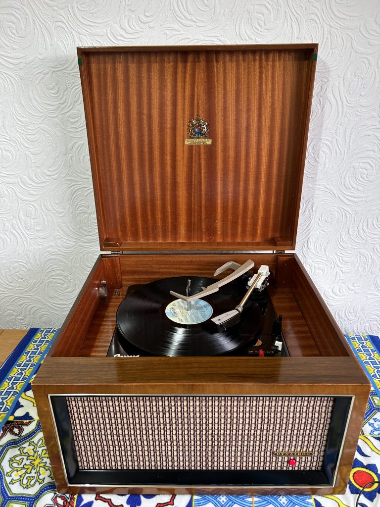
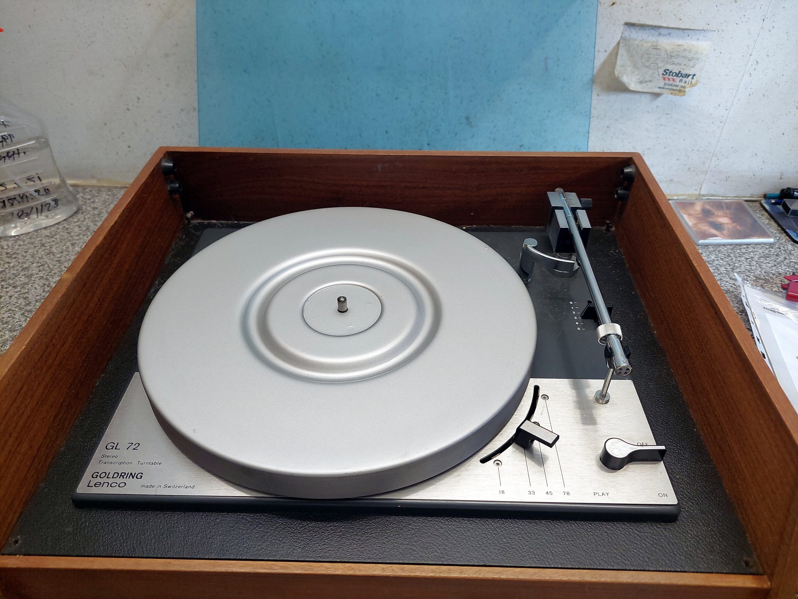
    I was recently given this nice Goldring Lenco GL72 by Alan of Timewarp Sounds, Ashingon.

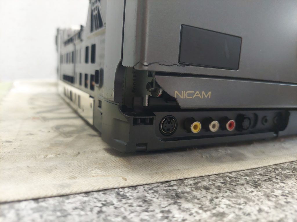
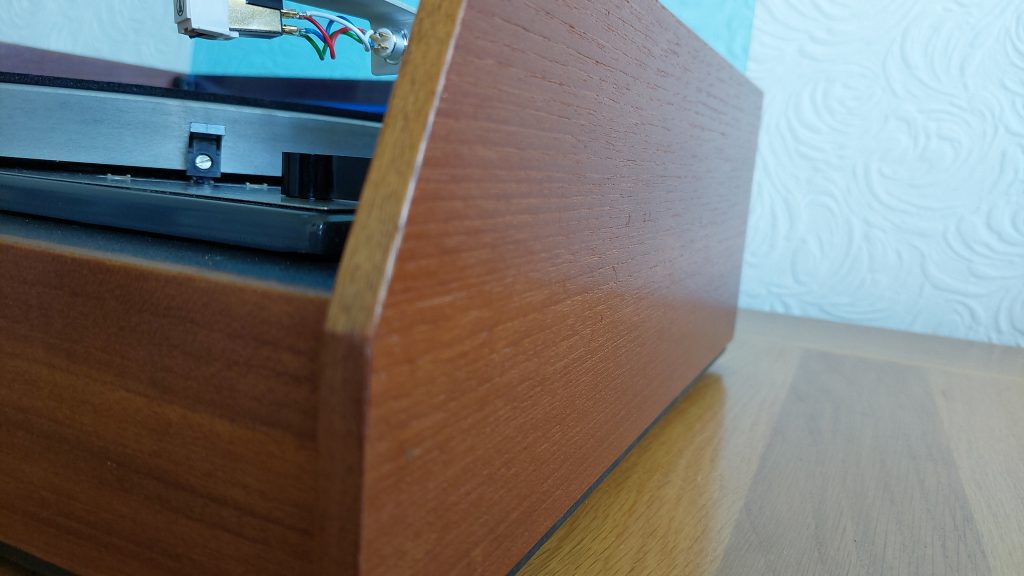
    It looked pretty good cosmetically under years of dust. The teak plinth was in good order too. Its perspex lid does have a small crack in it.

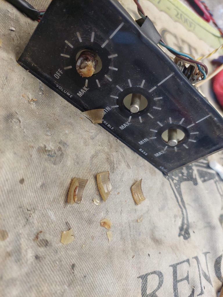
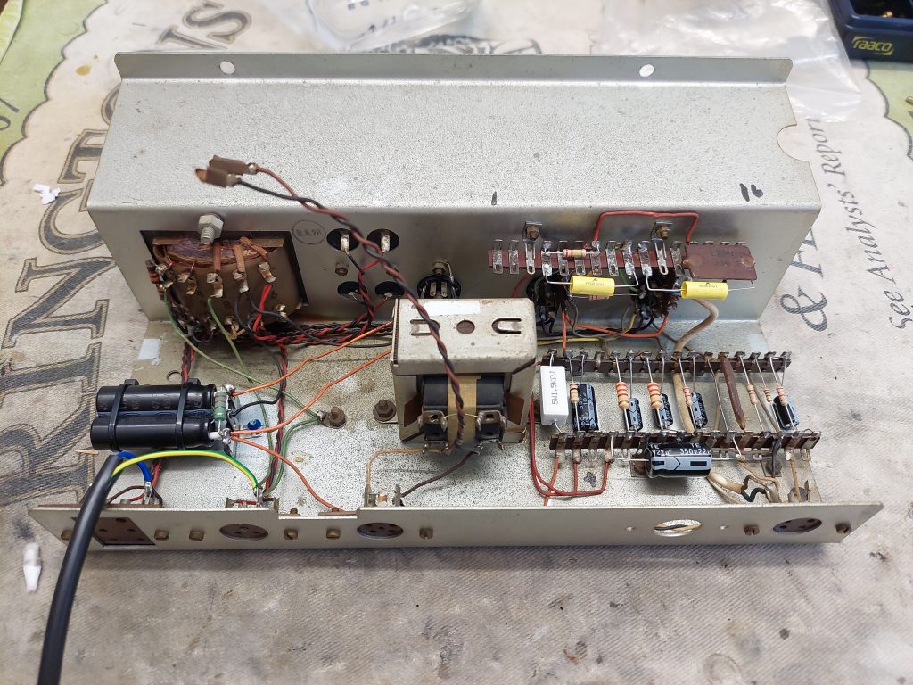
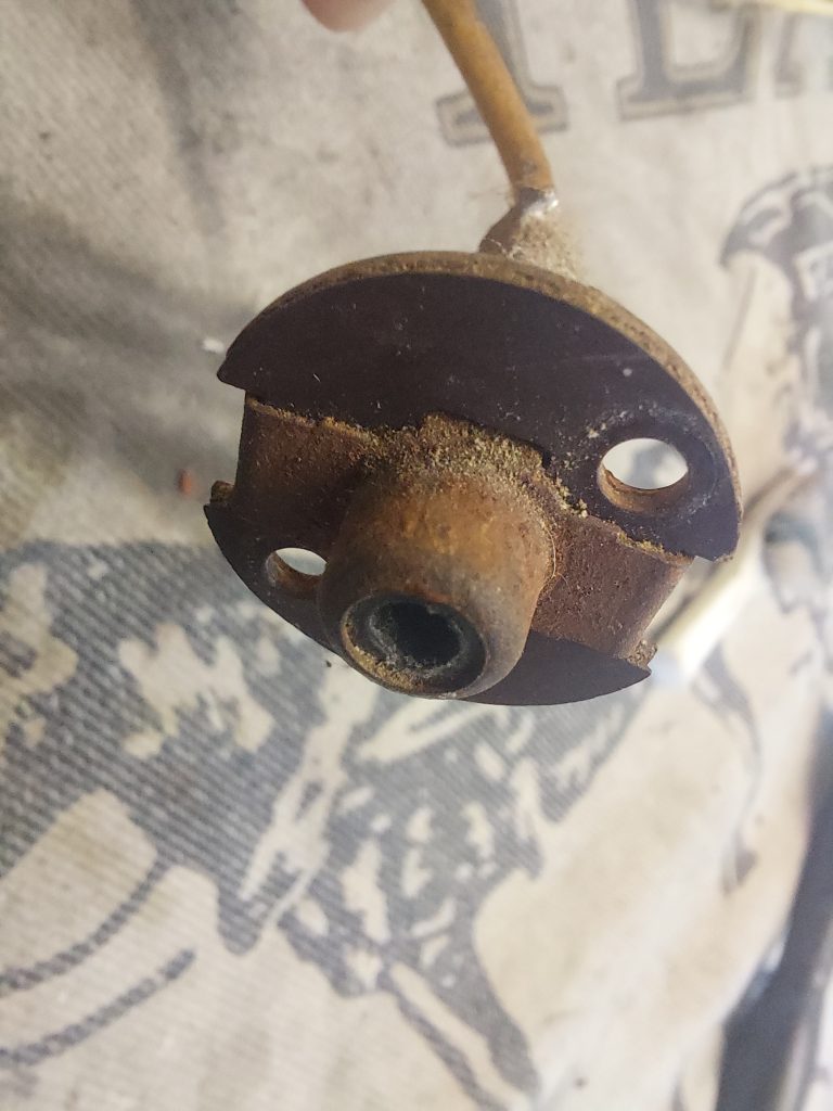
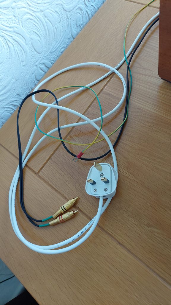
    The original rubber platter mat and headshell were missing, along with the cartridge. As with all of these old Lenco turntables, the v-blocks that make up the vertical bearing of the tonearm need replacing. All of the original mains and phono wiring needs replacing.

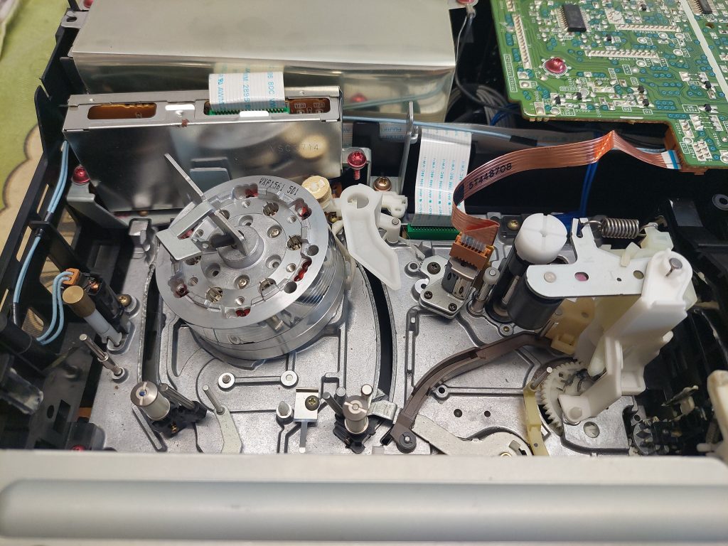
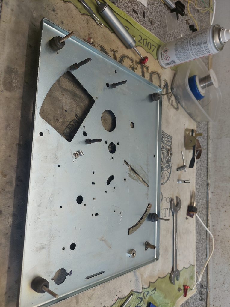
    My method of restoring turntables is time and effort intensive. I’ll try and give you an outline or the process. It involves stripping down the mechanism completely and putting all of the parts through an ultrasonic cleaner.

    Deck plate, all stripped down

    Next, all of the above deck parts are cleaned, polished and waxed to make them look as good as I can get them.

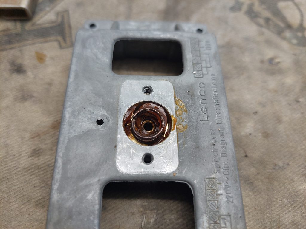
    The main platter bearing is stripped down and given a good polish with Autosol using a polishing wheel. The bearing housing is then packed with grease and put back together.

    Polished platter bearing

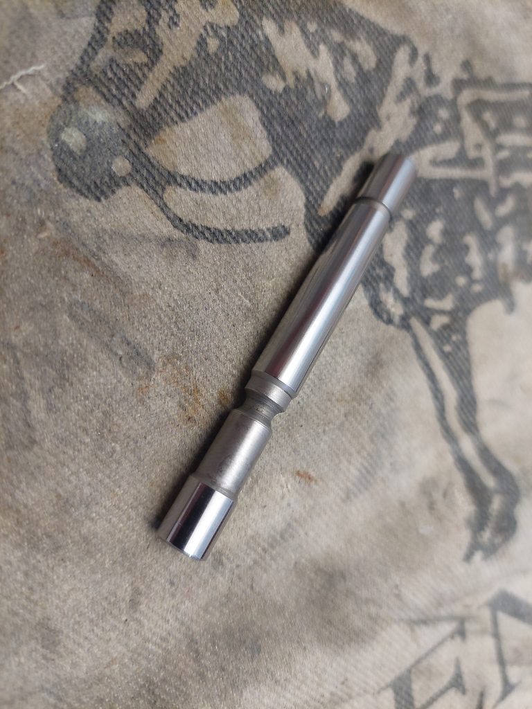
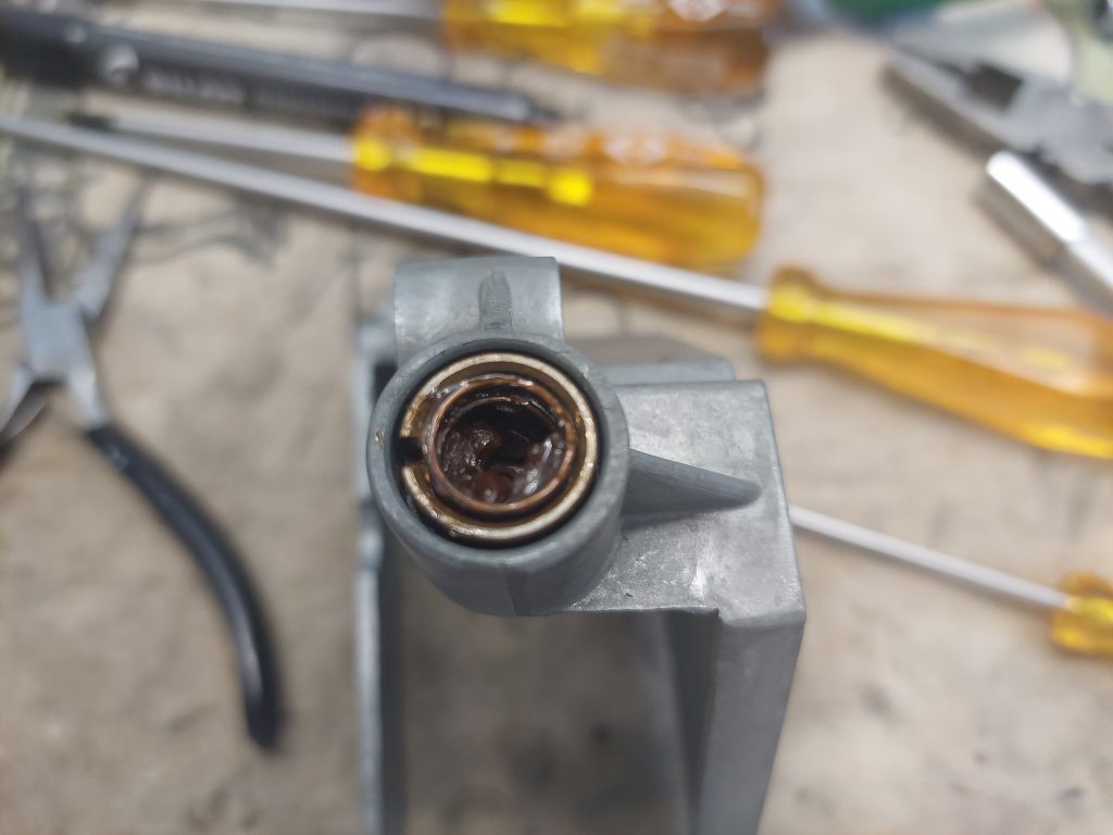
    The horizontal tonearm bearing was also stripped down. All of the surfaces that were in contact with the ball bearings were polished. The ball bearing races were packed with grease.

    Upper vertical bearing

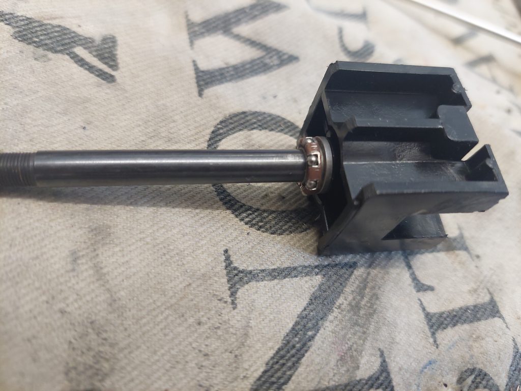
    This bearing needs careful reassembly. If the nut that keeps the assembly together is too tight, there will be too much friction and the bearing will have a ‘rough’ feel when you twist it. Keep backing off the nut until the bearing has a smooth feel to it.

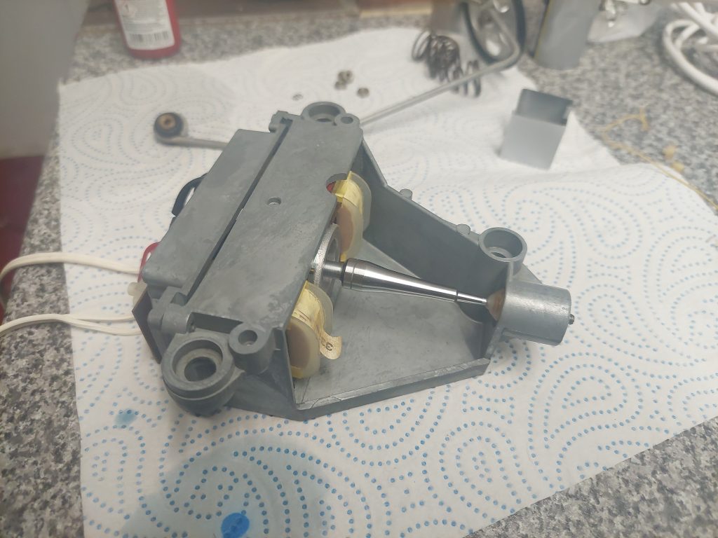
    Once everything has been cleaned, the mechanism it put back together piece by piece with the correct oil or grease where necessary.

    If a turntable has a dampened cueing arm, the mechanism is cleaned then reassembled with new silicone dampening oil.

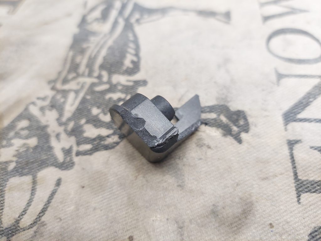
    New v-blocks were installed as the originals turn into mush. The replacements were made of a hard plastic. They did need a bit of adjustment with a file before they fit in their slot properly.

    The motor is treated in the same way. Strip it down, clean the bearings, re-oil them and resemble. I went the extra mile with this motor as I boiled the both of the motor bearings in oil. The warm oil is absorbed by the porous bearing material.

    Dried grease in motor bearing
    Dried grease in motor bearing
    Finished motor

    Once back together the motor can be given a few whacks with a mallet to properly align the rotor and bearings. The motor is then tested individually for quietness and true running.

    These Lenco motors have adjustable end play. This needs to be measured then reset to that measurement once the motor has been resembled and tested.

    Special attention is paid to making sure that the idler wheel is in good order.

    When the whole turntable is back together all of the initial setup adjustments can be performed as per the turntable’s instruction manual.

    The speed is calibrated using a mobile RPM measuring app. Each speed (16,33,45 and 78) has to be adjusted individually.

    A lot of testing finishes off the restoration process.

    Turntables take a lot of time to sort to a high standard. It doesn’t matter if the turntable is manual, automatic or an auto-changer, the common denominator is always time.

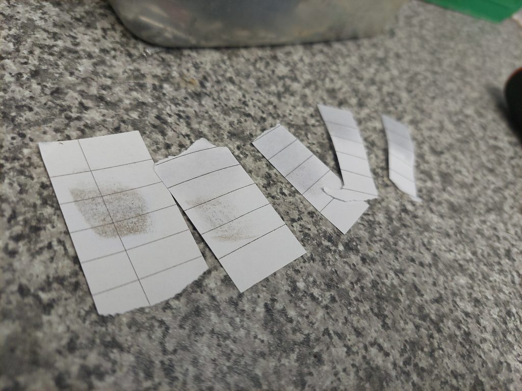
    You simply can’t get away with a drop of oil here and there. See the dried grease in the photos above. You need to go through them with a fine tooth comb for the sake of long term reliability and performance.

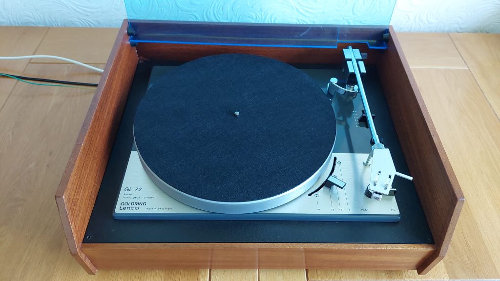
    The missing platter mat was replaced with a 12″, 3mm felt mat. I think it suits the turntable well.

    The headshell was replaced by a brand new part pre-fitted with an Audio Technica AT3600L. It looks a lot better than the original, clunky looking headshell.

    The AT3600L is my go to magnetic cartridge. They are brilliant performers.

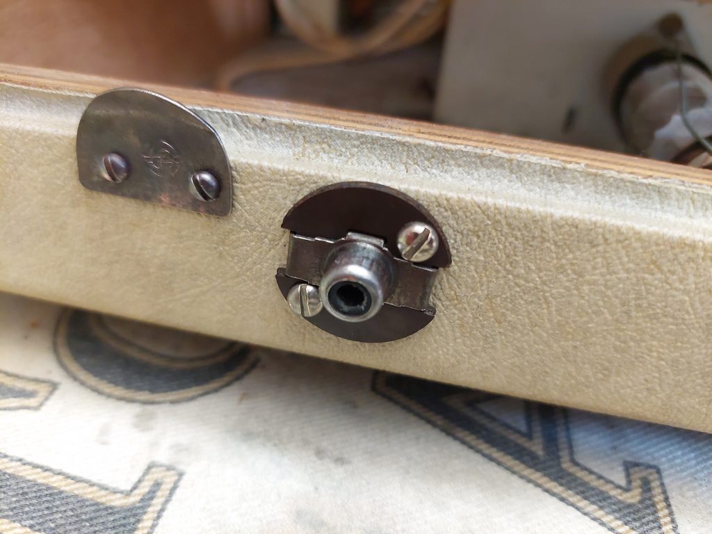
    To finish off the turntable, all of the mains, earth and phono wiring was replaced with new wire and connectors.

    New plugs and wiring

    The last job was to refinish the teak plinth. I recently ran out of both Danish and teak oil so I decided to use some decking oil from the shed. It’s likely to be all the same stuff. Smells the same!

    Apply the oil to a wad of fine wire wool and give the cabinet a firm rub down. Let the oil soak into the cabinet for about 20 minutes before using a disposable cloth to wipe up any excess oil.

    Oiled and waxed teak

    I find that this process gives a good looking finish and can be further enhanced with some furniture wax.

    The perspex lid was lightly scratched. A rub down with TurtleWax polishing compound smartened things up.

    Here is the finished result:

    Goldring GL72 all finished

    I’ve played a lot of records using this Lenco and I am impressed with the results. Definitely worth seeking these out!

    That’s it for now,

    C.T.H

  • Onkyo Integra A-8190 Restoration: Balancing Act

    Onkyo Integra A-8190 Restoration: Balancing Act

    I bought this amplifier from Alan of Timewarp Sounds, Ashington on a ‘spares and repairs basis. I thought it would be an interesting project.

    It is from 1987-1988 and one of Onkyo’s higher end integrated offerings. It has plenty of inputs and two tape loops if you are keen on recording to reel to reel or cassette tape. It also has composite video inputs so that you can connect more than one device to your old television. Handy in 1987, but useless now!

    At 100W per channel, it’s the most powerful amplifier I’ve worked on so far.

    Cosmetically, things were OK. The usual bangs and scrapes. The treble and balance knobs look like they’ve taken a bit of a knock and are a bit bent.

    Wonky treble

    The tape and video switch knobs all spun on their shafts. Hopefully the switches are OK!

    I also noticed that the volume control spins continuously. Not a good sign!

    My initial testing started by plugging in a pair of sacrificial headphone and feeding a signal into the tuner input. The LHC was quiet while the RHC seemed to work fine.

    Dirty amplifier

    Once I established what the fault was I decided I needed to give the inside of the amplifier a good clean. It was pretty dirty and looked like it may have been stored in a shed or garage for a long time. A thorough dusting with a series of soft bushes and a hoover removed most of the debris. The old Hoover Portapower I use for this has a handy blow function which goes a long way to vanquish hard to reach dust.

    I wanted to clean under the tuner, CD and phono input board. It’s a good thing I did because I noticed that the CD input RCA connector had some broken solder connections. These were easily re-soldered.

    Notice the cracked solder joints

    When the initial cleaning was finished I was ready to start the fault finding process.

    I started by reconfirming the fault. Yep, no LHC.

    Now I needed to isolate the location of the fault. Was in in the power-amp or pre-amp?

    I fed a signal into the CD input and pushed the ‘CD’ button, no LHC. Pushing the ‘CD Direct’ button brought back both channels!

    Why would the missing channel come back with the ‘CD Direct’ button pressed?

    According the the instruction manual for the A-8190, the ‘CD Direct’ feeds the input signals directly into the power-amp stage, completely bypassing the pre-amp. The only part of the pre-amp that is left in circuit is the volume control.

    This confirms that the issue is within the LHC pre-amp.

    I spent a little bit of time looking at the service manual as I planned my next move.

    During this time I wondered if the fault was mechanical rather than electrical?

    I powered up the amplifier, setting the input to ‘CD’. I noticed that if I manipulated the balance potentiometer in a certain way, the LHC would come in and out. This was a promising lead.

    To access the potentiometer loads of screws needed to be removed. The metal bracket can be removed to reveal a long PCB where all of the potentiometers are soldered.

    After the balance potentiometer was removed it was given a good clean with contact cleaner. Testing with a multi-meter revealed that everything worked as it should. I was pleased that the pot did not need to be opened or replaced!

    After re-fitting the potentiometer I took the opportunity to clean all of the amplifier’s many pots and switches. All of the rear RCA connections were cleaned too.

    Thankfully, the spinning knobs were just a matter of loose grub screws. They were all 2mm Allen screws.

    I also investigated the continuously rotating volume control. It looks like the internal ‘stop’ was broken, probably due to a heavy handed past owner twisting things until it broke. The volume control does work fine, so I’m not worried about this. As long as a future owner does not foolishly twist the knob the wrong way when listening to music, your speakers will thank you!

    The bent treble and balance potentiometer shafts were given a slight tweek to straighten them out.

    Once this was sorted, I put everything back together for another test.

    The LHC was now fully operational! The issue turned out to be a particularly dirty balance control.

    I let the amplifier warm up for an hour before I set the idle current.

    Idle current adjustment. Settled at 8.5mA, I’ll take it

    Once I was satisfied that all was well, I attached my Mission 761 test speakers to the amplifier and left it to play Serenade Radio to itself. I came back after a dozen hours and things were still sounding great.

    During the testing period, I cleaned up all of the front panel parts. The fascia, knobs and top casing were washed with soap and water to remove any dirt. A light pass with Brasso helped give things a light sheen. Everything was given a good rub down with Mr Sheen.

    The amplifier was put back together once all the testing was complete.

    I’m very happy with the results of this restoration. It is now a great looking and excellent sounding amplifier!

    That’s it for now,

    C.T.H

  • Panasonic NV-HS1000: A Quick Service

    Panasonic NV-HS1000: A Quick Service

    I was asked to have a look at this high end VHS deck by Alan of Timewarp Sounds in Ashington. I’ve done some basic servicing work on a few VHS decks so I was happy to help.

    The NV-HS1000 was a S-VHS editing deck that was intended for high-end consumer use. I believe that they are popular with those who digitise old VHS tapes.

    The main cosmetic issue was a broken hinge that was a part of the fold down control panel. The front flap that covers the VHS slot had a broken retaining peg.

    Before I started the servicing work, I tested the basic functions of the deck. Play, stop, fast forward and rewind all worked as they should.

    The head drum was cleaned with IPA soaked strips of paper. Plenty of dirt was removed. The rest of the mechanism was cleaned with cotton buds soaked with IPA. The pinch rollers, guide pins and other parts of the mechanism were pretty clean.

    Once the basic service was finished I tested the deck with a tape for the first time. Everything worked as expected.

    With everything working as it should it was time to tackle the broken hinge.

    The front panel was attached to the deck via a couple of screws and some plastic clips. Thankfully the service manual for this deck can be found online and offers some disassembly instructions.

    Once the panel was off it could be further disassembled into two parts. The bit I wanted was the front casing.

    The break was clean enough where the hinge could be super glued back into its original position.

    The two parts adhered together well. It’s not a pretty repair but rather a strong and functional one.

    The front panel went back together without any trouble. The panel could be opened and closed without issue. The hinged panel is dampened with silicone oil, which gives the deck a high end feel.

    Unfortunately I could not find the plastic pip that broke of the VHS cover flap, so it could not be reattached to the front panel.

    Once everything was back together the deck was given a rub down with Mr Sheen.

    More testing was done with the few VHS tapes I had to hand, namely the Star Wars original trilogy.

    Video quality was exactly what I expected from these old tapes. The VHS HiFi audio track was working too. The basic playback functions were rechecked and found to work fine.

    The original remote control was fitted with batteries and found to be fully functional. You can even use the remote control to set the time on the deck itself!

    The deck has so many features, most of which I can’t really test. The instruction manual can be found online which gives you an idea of what this deck can do.

    As a final test I played all three SW tapes which amounted to around six hours of testing.

    At this point, I was satisfied that the deck was ready to go back to Alan.

    Every now and again it’s nice to work on something that is outside my usual remit.

    That’s it for now,

    C.T.H

  • Hacker AL42 Stereo Extension Loudspeaker Restoration

    Hacker AL42 Stereo Extension Loudspeaker Restoration

    The Hacker AL42 was designed to be a matching stereo extension speaker for the Hacker GP42 ‘Gondolier’ record player. It also can be used as a standalone high quality mono amplifier.

    Throughout the late ’50s until the early ’70s, it was common for record player manufactures to offer an extension speaker which let buyers convert a compatible mono player to stereo operation.

    Usually, these extension units can be hard to find (though not impossible) as they sold few of them compared to the main record player unit.

    The main driver of this was price. In the late ’60s a single play GP42 cost £37/6/0 and the AL42 cost £17/17/0. That’s £55/3/0 altogether. You can see why some customers didn’t bother!

    All you needed to setup your GP42 for stereo was an AL42 extension speaker, a special stereo lead, a stereo phono cartridge and of course, stereo records!

    Despite being called ‘stereo extension speakers’ these were not just a separate speaker in a cabinet like what you had with radio extension speakers of the past. They were fitted with their own amplifier which was identical to main unit.

    Anyway, on to the restoration:

    Amplifier and Chassis Cleaning:

    I bought this AL42 from eBay in September of 2023 and have just recently sorted it. I bought it to go with the Gondolier (still unrestored)I bought the year before.

    It was a bit rough cosmetically, but nothing that couldn’t be sorted.

    Mucky cabinet

    The cabinet was filthy but it responded well to a thorough scrub down with Vulpex. Once dry, the cabinet was given a coating of beeswax to give it a bit of a sheen. The cream fabric had yellowed a bit. Not much can be done about this, I’m afraid. Just focus on getting things a clean as you can.

    Mucky grille

    The grille was similarly filthy and cleaned the same way as the cabinet. The Vulpex cut through the grime but had a little bit of trouble cutting through the brown drip like stain that can be seen above. The staining on the finished grille is only noticeable at certain angles.

    The Hacker logo got a well deserved polish too!

    Dusty valves

    The inside of the cabinet and amplifier was thick with dust. Once the amplifier was removed from the cabinet, any debris could be removed with a selection of brushes and a hoover. Having a hoover that can blow air can be handy for removing stubborn dust.

    Filthy chassis

    When it comes to cleaning an amplifier chassis I like to get it as clean as I can by using brushes and a hoover. I do think this ‘dry-cleaning’ method produces exceptable results 99% of the time. If I decide that something is exceptionally filthy, there is always the option of ‘wet-cleaning’ the chassis with foam cleaner. This has its own risks, of course. You will have to make sure that any cleaner has completely evaporated before the amplifier is switched on.

    Original knobs, missing round trim pieces

    The clear knobs Hacker used here are notorious for becoming brittle. It’s likely that they will break when removed. That’s what happened to me. It’s not a problem as many off the shelf replacements can be used. A 3D printed set are available on eBay.

    Later GP42 and AL42 units were fitted with a different type of knob that doesn’t have this issue.

    Broken brittle knobs

    The perspex ‘dial’ behind the knobs can be polished then waxed.

    Once the cabinet and amplifier were clean, it was time to focus on restoring the amplifier.

    Restoring the Amplifier:

    This amplifier was used in a handful of Hacker record players throughout the ’60s. This will be third I’ve restored.

    The valve line up is ECL86 X2 and EZ80 X1. They look to be the factory fitted Mullard types.

    Dusty valves

    ECL86s are known to develop internal leakage when they have been heavily used. It is important to check for this once the amplifier has been sorted. NOS ECL86 valves can be bought online, but expect to pay upwards of £35.00 each or £80.00 for a pair. Second hand, sometimes tested, valves can be found for much less. This could be a gamble as you can’t gauge how leaky a given valve is without testing it in circuit.

    Clean valves

    Once the amplifier was on the bench I needed to asses whether or not it would be a viable restoration project.

    The resistance of the primary and secondaries of the mains transformer and audio output transformer were measured and found to correspond with the measurements given in the service manual.

    The large Goodmans 10″x 6″ speaker was also found to be in good order. It just needed a good dusting. There was also no rubbing between the voice coil and the magnet.

    All of the potentiometers and mains switch were cleaned with contact cleaner. The mains switch needed extra cleaning to make sure that there was as little resistance as possible between the switch contacts when they were closed.

    Each valve and valve socket had its pins cleaned.

    Since the above were all OK, the restoration could begin.

    I start by measuring the resistance of all twenty-one resistors. Anything out of tolerance is replaced. I ended replacing every resistor bar two.

    All of the replaced components

    Both grid coupling capacitors were replaced.

    All four cathode bypass capacitors were replaced along with all four HT smoothing capacitors.

    The dual section 47μF can was replaced with two separate capacitors that were soldered to some tag board. The original CCL capacitor tested perfectly but I like to replace them just in case they go wrong in the future.

    A new mains lead and plug finishes off the amplifier.

    Replacing all of these components does take a good deal of time and effort. I do enjoy it though. I do think it is worthwhile for reliability purposes. Remember these amplifiers are getting close to sixty years old!

    The finished amplifier

    Once all of the capacitors and resistors have been replaced the amplifier can be switched on for the first time.

    The initial power up is done via a lamp limiter to make sure that excessive current isn’t being drawn by the amplifier.

    The initial power up was uneventful. The HT gradually rose to 270V and I was rewarded with the sounds of Serenade Radio from the speaker. It sounded good with plenty of volume. The tone controls both worked as they should.

    After working for an hour I measured all of the valve voltages and everything checked out as it should.

    Clean valves back in the amplifier

    Once I was satisfied that everything was in order I let the amplifier play to itself for six hours. During this time I monitored the voltage on the grid of the pentode section of both ECL86s. 300mV was measured here, nothing to worry about. If this figure was much higher, multiple volts etc., that would be a cause for concern.

    I quite like how Hacker designed and laid out this amplifier. It’s very easy to work on. Especially the row of resistors and capacitors on the right hand side of the chassis.

    The last thing to do was to assemble everything back in the cabinet.

    Crusty input socket
    Input socket after being cleaned with a fine wire wheel

    Overall, I think this restoration went really well. These AL42 units sound excellent once they are properly sorted. Plenty of bass. They are sometimes criticised for their lack of treble but that is going to be the case with such a large speaker and no tweeter fitted. Careful adjustment of the tone controls will help here.

    In my experience, a lot of these valve record players don’t have heaps of top end. Its just how they are. You need to let your ears tune themselves to what they are hearing, if you know what I mean?

    Here are a few photos of the finished AL42 to round things out:

    The finished AL42
    The finished AL42
    The finished AL42, notice the new knobs

    It’s another Hacker saved, which it its own reward.

    It will be interesting to pair it up with the GP42 once it has been restored.

    That’s it for now.

    C.T.H

  • Murphy Majorette: 50/50

    Murphy Majorette: 50/50

    The nice thing about working on equipment I’ve already restored is that the list of suspect components is quite small. This really helps to focus the faultfinding process.

    I restored this Murphy Majorette A852G in June of 2024 where it had all of the usual work done. Recently, its owner got in touch to say that a bit of distortion could be heard when playing a record. I was happy to see the player as soon a possible.

    I initially suspected two things: a valve issue or a BSR X5M cartridge that was due for a rebuild.

    I started my investigation by feeding the amplifier a signal via an old iPhone. After listening to a bit of Serenade Radio, I could hear some distortion. It was subtle and most notable at lower frequencies. This ruled out the cartridge being faulty. Time to get the amplifier out of the cabinet.

    Removing the amplifier out of the cabinet is a bit of a pain due to everything being hard wired together. You almost remove the record deck, the front panel controls and the amplifier chassis as one thing.

    Looking at the component side of the amplifier I noticed that the cathode resistor (180Ω, 0.5W) for the UCL82s pentode was blackened. I wondered if something was causing the pentode to over bias slightly? Not enough to cause catastrophic damage, but just enough to give rise to a bit of distortion.

    I set up my multimeter probes to measure the grid voltage of the pentode. After letting the amplifier play to itself for about ten or so minutes, I noticed the grid voltage had risen to 8V when it should be at 0V. The voltage across the cathode was 11.5V. It’s no surprise that the cathode resistor had been getting warm when the cathode current was 64mA and the resistor dissipating 0.7W!

    Since the grid coupling capacitors were new I did not suspect that they were leaky. I concluded that the ‘Telam’ branded UCL82 had became internally leaky and needed to be replaced.

    A NOS Matsushita UCL82 was sourced and fitted. The grid voltage is now 0V. Well, it stabilised at about 45mV over a period of 4 hours of continuous testing. This is absolutely fine. Cathode voltage and current were now a much more healthy 8.2V and 45mA respectively.

    After a few more hours of listening I was satisfied that there was no more distortion and the fault had been cleared.

    The blackened resistor was also replaced.

    Finally, everything was put back together and I gave the cabinet a quick once over with wax.

    C.T.H

  • Welcome to the Hails HiFi Blog

    I intend to use this blog to write about various topics relating to the repair and restoration of vintage HiFi equipment.

    This blog will mostly be written summaries of restoration projects and the odd repair.

    I hope that these future posts give potential customers a good idea of what goes into restoring equipment to my own high personal standards.

    That’s it for now,

    C.T.H

    Dynatron Cavalcade, restored in 2023, enjoying some ‘Hooked on Classics’.